Background
The first NFPA 13 document was published in 1896. This document did not have any stipulations regarding sloped ceilings and how they would impact sprinkler layout, water flow necessary for fire suppression, or how big the water supply would be that supports the operation of all the fire department connection sprinklers. For horizontal ceilings, it was believed that if there was a slope, more sprinklers would be activated and there would be a greater demand for water from the system. However, most of the fire tests that were conducted to substantiate the requirements of NFPA 13 were conducted with horizontal ceilings. Therefore, the discussions were speculative.
For the first approximately 75 years, this was not a major issue. This was because the strength of the water supply was determined based on a piping layout with no consideration for branch hydraulic calculations. Additionally, the number of combustible materials was limited, and so were the heights of the stored materials, meaning the impacts of the sloped ceilings were limited. This began to change in the 1970s. However, sloped ceilings in most sprinkler systems were not addressed because NFPA 13 did not provide any requirements and it was not known what would be required.
Recent History
The NFPA committee started to analyze sloped ceilings in more detail while developing the 1996 edition of NFPA 13. Initially, the committee decided that they would refer to sloped ceilings as those that have a rise over run ratio of greater than 2 in 12. The NFPA decided that a 30% increase to the design area would work in all three categories, light, ordinary, and extra, in the context of providing water to all the sprinklers that would most likely be activated in a fire, including the remote sprinklers most likely to be activated by the hot gases from the fire. The NFPA also resolved two other problems as well: the design area would most likely be provided along the planned branch lines, and since most branch lines run up the ceiling slope, would most likely serve the sprinklers that would be activated in a fire.
Determining that a sloped ceiling is one that exceeds 2 in 12 was based on work done with small models by the brilliant research scientist, Gunnar Heskestad, at Factory Mutual. Heskestad found that with a 2 in 12 slope, the movement of heat under a horizontal ceiling and a sloped ceiling was similar. However, with slopes greater than 2 in 12, the movement of heat began to change and skew upwards along the slope.
The 30% increase was at best a rough guess. The committee did not possess data to move the level up by a specific factor as the committee assumed that the proposed increase would be enough to address the concerns for light, ordinary, or extra hazard scenarios. The committee was unsure on the levels necessary to protect storage. The issue was compounded by the fact that the committees for general storage and rack storage were different and therefore the requirements were found in different standards, which did not directly address the issue.
For the next edition of NFPA 13 (1999), all the protection requirements for storage were included in NFPA 13, and it was decided that for the time being, the protection of storage under sloped ceilings would not be included in the standard until more information was available. This was the position until the 2025 Edition.
For about 12 years after the 1999 NFPA 13, the NFSA attempted to attract the interest of other parties, such as the insurance companies, the manufacturers, the big box retailers, and the warehouse owners, to fund research about sloped ceilings. However, there was no interest in the funding. In 2012, Ken Isman, the then Vice President of Engineering of the NFSA, took the initiative to create a process that would allow engineers to define the specific conditions of a sloped ceiling storage area. As part of the process, engineers would be required to create a computer model of the fire behavior that would develop under a sloped ceiling, which would be a challenge to do.
To prove the process and help with the modeling, the NFSA engaged professors at the University of Maryland with a start-up company they formed, Custom Spray Solutions. The NFSA and Custom Spray Solutions modeled rack storage of Group A Plastics and Class II commodities with a height of 20 feet under four different ceiling types, a horizontal ceiling, a 2 in 12 slope, a 4 in 12 slope, and a 6 in 12 slope. The results determined that the 2 in 12 ceiling and horizontal ceiling were relatively the same, and that the 4 in 12 ceiling and 2 in 12 ceiling were relatively the same, and was a big surprise to everyone. A 6 in 12 ceiling slope significantly skewed the sprinkler openings along the slope and caused a significant number of openings along the slope to be remote from the fire.
Thanks to the NFSA and Custom Spray Solutions’ successful models, the Fire Protection Research Foundation (FPRF) could create a research project with many collaborating insurance companies and stakeholders providing research funding. The research team focused on new models, conducted water spray tests with various configurations of both floor-mounted and ceiling-mounted sprinklers, and advanced full-scale fire test programs during the third phase of the project, which spanned from 2015 to 2020. The “Phase 0” part of the project, which the NFSA led, inspired the collaborative fire safety research. The project provided sufficient research to establish new design principles, which were unfortunately beyond the last minute to be published in 2022 NFPA 13. A dedicated group was created to advance the requirements to the 2025 edition of NFPA 13.
Discharge Criteria for Light, Ordinary and Extra Hazard
Regarding the design of the ceiling slope above 2 in 12, the committee presented the design professional with four options, categorized as light, ordinary, and extra hazard:
- Proposed a horizontal ceiling drop, with tiles that remain in place against an uplift of 3 lb/ft2, and with designated sprinkler protection.
- Proposed an increase in the design area of 30%
- For ceiling slopes of 4 in 12 and less, with no other changes to Chapter 19 requirements:
- Solid purlins supporting the roof deck run across the roof slope.
- Purlins do not exceed 18 inches in depth and 5 feet on center.
- Solid major structural members do not exceed 40 feet on center.
- Blocking is provided above the purlins or beams if they are open.
- For construction that is obstructed and has ceiling slopes of 4 in 12 and less, provide sprinklers in every channel, with no other changes to Chapter 19 requirements.
The first option has been provided for some time, but this is the first time it has been referenced in NFPA 13. The concern is that a ceiling creates a concealed area above the ceiling, which has to be protected by sprinklers unless the construction above the ceiling is either non-combustible or of limited combustibility. The creation of a concealed space also eliminates available three-dimensional space that can be used for storage.
The suspended ceiling must be designed to meet the fire plumes mobility criteria. This can be accomplished with heavy ceiling tiles or by securing the tiles. This can be very expensive.
The second option can be found in NFPA 13, 1996, and all subsequent editions. Even though there has been no investigation into the 30% increase in the design area, this increase has been a part of the standard for 30 years, giving it a reasonably good record. Legally, it has “stood the test of time.” There was a submission to the 2025 edition to eliminate this option. The sprinkler committee, however, wanted to keep this standing, as it is the least expensive option when compared to all other listed options.
The third option is where the substantive findings of the NFSA and FPRF research lie. Using this option, NFPA 13 discharge criteria for horizontal ceilings may be applied to sloped ceilings with a slope up to 4 in 12, without changes or modifications, where the roof/ceiling assembly contains enough obstructions to impede the upward movement of the heated layer along the slope. The obstructions are usually the smaller structural elements, which in NFPA 13 are called purlins. They are required to be solid. Along with the solid smaller structural elements, the larger ones are also required to be solid and the normally open framing above the larger structural elements must be closed. This is a significant deviation from the traditional method of construction.
Refer to Figure 1. It provides a depiction of buildings with a sloped ceiling. Here, the solid structural components are dark gray. The purlins are on top of the gray solid structural components and/or the gray structural components. The gaps between the purlins are closed. During a fire, hot gases cannot pass through closed spaces. Per NFPA 13, the definition of “blocking” is purposefully broad where “blocking” is designed to contain the flow of hot gases. As explained in Section 3.3.22 and the related annex note, if the construction is of a combustible nature, then “blocking” may be of a combustible nature. If the construction is of a non-combustible nature, then “blocking” of the non-combustible nature is required. It is permitted if, in “blocking,” the flow of hot gases is not completely sealed.
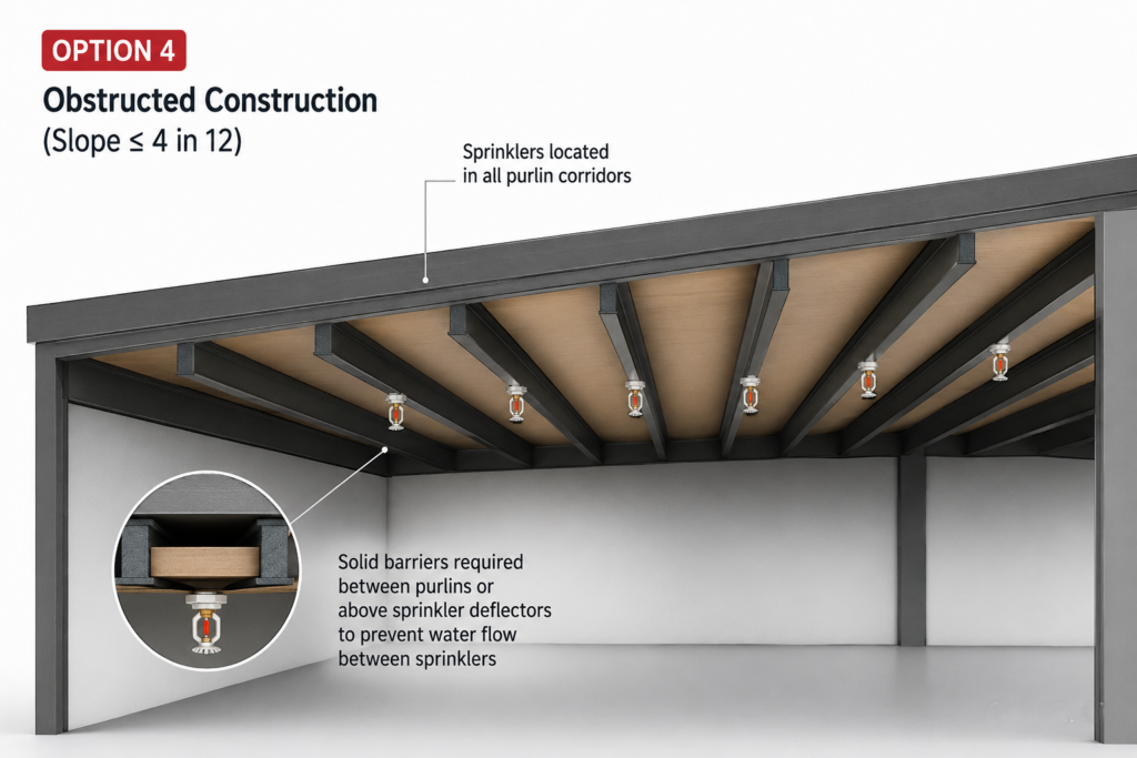
Figure 1. Open spaces which are located above the gray structural components and spaces between purlins. These gaps must be sealed to prevent the flow of hot gases to the remote area sprinklers.
The third option delivers fire protection with a minimal water supply. However, it does present some issues with building construction. For the option to be used cost-effectively, the designer of the sprinkler system must collaborate with the structural engineer to allow the system to be used in a cost-effective way for the building owner.
The fourth option, also from the NPRF research project, is available when the construction is defined as “obstructed” with a slope of 4 in 12 or less. It is highly likely that the sprinklers that will be in all the corridors made by the purlins will be the first to activate and control the fire. Purlins are typically installed at a spacing of 4 to 5 feet. This means that the sprinklers will be installed at a spacing that is less than what is prescriptive in the NFPA 13. In this case, if the purlins are not solid, or if the sprinkler deflectors are below the purlins, solid barriers will need to be installed to prevent one sprinkler from flowing into another.
Storage Discharge Criteria
When designing a protection system for a storage hazard, the committee gave the design professional five alternatives. The first four alternatives listed can be used with any type of sprinkler (CMDA, CMSA, or ESFR). The fifth alternative is limited to spray sprinklers (CMDA).
- Follow the requirements for in-rack sprinklers in Section 25.7
- Provide a horizontal drop ceiling (and the same upward for rules in Chapter 19).
- For unobstructed ceiling construction with a roof slope of 4 in 12, utilize the provisions of Chapters 20 to 26 and increase the design area by 50%.
- For obstructed construction with a roof slope of 4 in 12, utilize the provisions of Chapters 20 to 26 without a design increase (and the same construction requirements as Chapter 19).
- For obstructed construction protected with spray (CMDA) sprinklers and a slope of 4 in 12, provide sprinklers in every channel (the distance between closely spaced structural members)
The first option applies only to rack storage. In Section 25.7, numerous in-rack sprinklers are required that surround the potential fire. Because no storage is allowed above the in-rack sprinklers, the in-rack sprinklers should control the fire in the rack without the ceiling sprinklers needing to operate. All the fire tests performed with the in-rack arrangement of sprinklers have controlled fire without the operation of ceiling sprinklers. While these tests were not performed under sloped ceilings, the heat required to operate sprinklers under a horizontal ceiling was not achieved. Therefore, the same should apply to sloped ceilings.
Since ceiling sprinklers do not control fire, the water supply does not have to provide water to ceiling and in-rack sprinklers at the same time. Because of this, ceiling sprinklers can still be placed for extra measure. The ceiling or the in-rack determined the demand on the water supply, and the other was not required to be considered, or the total demand. The in-rack and ceiling demand did not have to be combined. Likewise, the demand for ceiling sprinklers would not have to be equal to the demand for in-rack sprinklers.
The second option would be the same as previously discussed in protecting against light, ordinary, and extra hazards, so elaboration would not be necessary.
The third option is taken from the research project, which found that for ceiling slopes of up to 4 in 12, increasing the design area by 50% would suffice to control fire in the area. In certain types of unobstructed construction, this may be the most economical option.
The fourth option is the same as what was previously discussed in relation to protection against light, ordinary, and extra hazards, so it does not require further discussion
The fifth option applies only to buildings that use obstructed construction that has a slope of 4 in 12 and to buildings that are protected by spray (CMDA) sprinklers. Under those conditions, the design professional may choose to install sprinklers in each and every channel created by the purlins. Because the design area will incorporate all of the sprinklers within a specified area, this will lead to a significant increase in the number of sprinklers in the design area. Furthermore, the spacing of the sprinklers will more than likely be close together and will require a solid construction barrier between the sprinklers so that the water spray from one sprinkler does not directly impinge upon the adjacent sprinkler.
Orientation of Sprinklers
At the outset of the discussion of the protection of buildings with sloped ceilings, the question would be whether the protection sprinklers would be more effective if the deflectors were installed parallel to the sloped ceiling or the protection sprinklers were installed with the deflectors parallel to the horizontal floor. For more than a century, the preferred method of installation has been to install the protection sprinklers with the deflectors parallel to the sloped ceiling for the following reasons:
Due to the hangers’ placement and how branch lines and purlins interact, the installation offers various hangers. Purlins, as smaller members, usually run along the roof slope and will be perpendicular to the branch lines. Using this technique, the sprinklers will be Tee’d on the branch line, as illustrated in Figure 2.
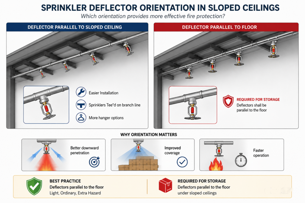
However, the benefits listed above are cost-oriented, and so does the branch line arrangement. The order of the lines on the slope also impacts fire protection physics; which of the following will concern us:
Sprinklers, which serve fire protection for Storage, can have a downward thrust to help penetrate the fire suppression curtain formed by a vertical hot gas plume. If the angle of the branch line is sufficient, the droplet may be carried away by the curtain of gas and would not penetrate the plume.
By the branch line having a slope, the adequate coverage of the area (especially the one below the line) by the water curtain formed by the droplet is not guaranteed, as the area just above the branch line may be covered. Additionally, if the fire is just below the line, it may also take a considerable amount of time before the line is opened.
Much effort was devoted to the research project to determine the most effective orientation. Ultimately, it was decided that when the sprinklers defend against light, normal, or extra hazard situations, the best practice is to install the sprinklers horizontal to the floor. However, installing the sprinklers horizontal to the ceiling is also an acceptable practice, and so both will be allowed.
When the sprinklers defend against the storage located under a sloped ceiling, the deflectors will be required to be horizontal to the floor. This will necessitate a different method of installation. Contractors will need to rely on innovative ways to keep the costs of sprinkler installations low.